Water level gauges are general purpose gauges, but should not be used for oxygen. The water level gauge can be easily identified by the label found on the face of the gauge.
Although water level gauges belong to the pressure gauge family, their installation process is slightly different compared to liquid and dry pressure gauges.
We have included detailed diagrams to provide examples and steps to ensure that your water level gauge is accurately installed. In this blog, we will start with a brief description of what a water level gauge is then we will walk through the 3 steps you will need to properly install your water level gauge.
Water Level Gauges
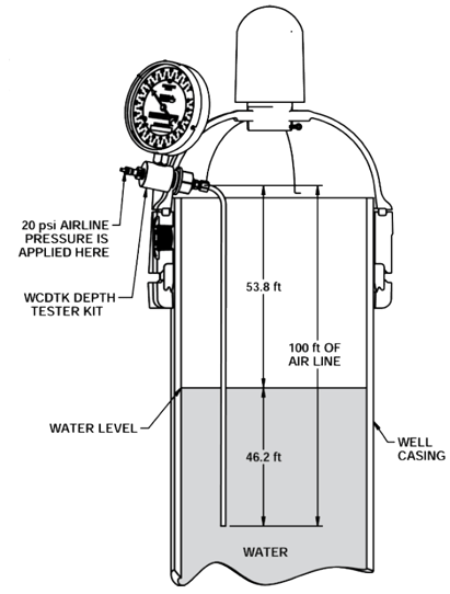
Water level gauges include an extra large dial face with a re-adjustable pointer. The adjustable dial ring is specifically set for the length of the air line. The air pressure is applied to the air line by purging the air line of any water which causes the pointer to move away from the stop pin, in a clock wise direction. Once the air line has been completely purged of the water, the needle will remain still, indicating what the water level is in feet from the surface, see below diagram.
In the below example, you can see that there is 100 ft of air line. The air line consists of a small diameter pipe or tube that is long enough that it can extend to a point roughly 20 ft below the lowest anticipated water level.
It is important to ensure that the air line is hanging vertically without any bends or twists in it, with the exact length being known. In the diagram, the bottom end of the air line is 46.2 ft below the surface of the water. To figure out the water level from the top of the well, you minus 46.2 from 100 to get the distance of 53.8 ft. When the air is blown into the air line, the needle on the water level gauge will show that the water level is 53.8 ft, as shown in the example below.
Installation Process
Step 1:
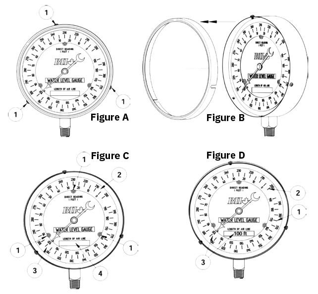
First, to change the setting of the adjustable dial ring, you will need to loosen the three screws that are on the outside of the gauge (Fig. A-1). Then, you need to remove the ring and glass from the gauge (Fig.B).
Step 2:
Next, you will need to loosen the three lock screws on the gauge face (Fig.C-1) while rotating the outer disc (Fig.C-2). The easiest way to achieve this is by pressing your fingers on the surface near the outer edge until the air line length, that's on the dial, aligns with the needle (Fig.C-3).
The length of the air line should be marked in the block provided on the inner dial (Fig.C-4), which provides a permanent record of the length of the airline for easy reference (Fig.D).
 The diagrams are an example of 100 ft of air line.
Step 3:
You can then properly take a reading. The reading is taken on the inner scale (Fig.D-1), if the air line length is up to 190 ft. If the air line exceeds a length of 200 ft, you can perform the same procedure as above, except that the reading needs to be taken on the outer scale of the adjustable dial ring when the water level exceeds 190 ft from the surface (Fig. D-2).
In Conclusion:
Water level gauges are important gauges and when properly installed, accurately measure the level of water from the top of the well. Refer to the diagrams throughout your installation to ensure you don't miss an important step.
Have further questions about this subject?

Head over to Boshart's Knowledge Base: technical product information, guidelines, and more.
![[Video] When to Select a Liquid VS Dry Pressure Gauge](https://blog.boshart.com/hubfs/gauge.png)
SHARE