Do you have trouble with properly installing compression connection sump pump check valves in your effluent of sewage system? Well, you’re in luck!
In this blog, we will go over when a compression connection valve is used, the options you have when picking your compression connection valve, and the steps needed to properly install a compression connection valve in a sump pump, effluent or sewage system.

Compression Connection
A compression connection is used to join a valve to IPS (Iron Pipe Size) piping and it provides a means to connect a PVC valve to PVC piping, without the use of primer and solvent cement. Compression connections also allow for the joining of two dissimilar materials with the IPS outside diameters. Making a watertight seal requires the compression nut to be tightened to compress the gasket to seal against the pipe.
Before installing, you must design the system piping layout and determine which valve is best for your sump pump, effluent or sewage system.
Compression Connection Valve Options
A PVC Swing Check Valve, which provides reliable back flow protection, along with a designed angle seat to minimizes flow reversal, and potentially damaging hydraulic shock.
PVC Ball/Swing Combination Valves feature both an in-line shut off and back flow prevention which makes it a compact option, along with a designed angle seat to minimizes flow reversal, and potentially damaging hydraulic shock.
Both valves are available in a standard or quiet option.
Now that your are equipped with this knowledge, you are now ready to go through the steps to complete a compression connection for your sump pump system.
INSTALLATION STEPS
Step 1 - Design the system piping layout and cut piping to the appropriate length.
The proper location for the check valve is close to floor level, to both minimize the volume of water which drains back at the end of each pumping cycle, as well as to have the valve in a convenient location for easy inspection and servicing or replacement of the valve.
- Piping must not be smaller than the pump discharge.
- A minimum of 2 feet (0.61 m) of static head is recommended over the check valve for positive sealing.
- In an Effluent system, the pipe must be capable of handling semi-solids of at least 3/4” (19 mm) in diameter.
- In a Sewage system, a 2” valve MUST be used, and the pipe must be capable of handling semi-solids of at least 2” (51 mm) in diameter.
- VERTICAL installation is recommended when pumping solid free liquids.
- HORIZONTAL installation is critical when pumping solids or semi-solids, if necessary, valves can be installed up to 45°. Vertical installation could result in solids settling back down onto the valve, preventing the flapper from opening when the pump starts.
- Some pump manufacturers recommend drilling a vent hole to prevent air-locking of the pump (typically located in the basin between the pump and check valve). Refer to pump installation instructions.
Step 2 - Clean both pipe-ends and slip sockets of the valve.
Step 3 - Mark both the inlet and discharge pipes (refer to installation instructions for appropriate length).
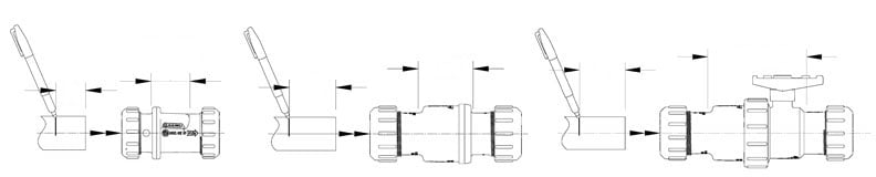
Step 4 - Remove the compression nuts by turning counter-clockwise. Remove the compression gaskets.
Step 5 - Slide the inlet compression nut followed by the gasket over the discharge pipe from the pump until it covers the marking from step 3. Slide the valve body onto the discharge pipe until it bottoms out. Ensure the flow arrow is pointing away from the pump, then slide the compression nut and gasket towards the valve body and hand tighten the compression nut.
Best practice is to install valves in the VERTICAL position when pumping solid free liquids.
When pumping solids / semi-solids valve must be installed HORIZONTALLY (up to 45° angle acceptable, see #1). Extra care must be taken to ensure the flow arrow points away from the pump and the check valve body is oriented as per the marking on the valve body “HORIZONTAL USE THIS SIDE UP”. Failure to position the swing check valve with the hinge of the flapper in the top center position will result in the valve not functioning properly.
Step 6 - Slide the outlet compression nut followed by the gasket onto the discharge pipe from the check valve until it covers the marking from step 3, position the discharge pipe into the valve body ensuring it bottoms out. Then slide the compression nut and gasket towards the valve body and hand tighten the compression nut.
Step 7 - Double check the markings on the pipe (Step 3) are flush with the ends of the compression nuts.
Step 8 - Tighten the compression nuts 3/4 to 1 turn with a spanner wrench or strap wrench. Average torque should be approximately 25-foot pounds for valves up to 2” in size.
Step 9 - Properly support and restrain discharge piping, the pipeline must be restrained to prevent lateral movement by end blocking at direction changes and at any reduction in pipe size.
Step 10 - TEST your connection to ensure a leak-free seal.
In Summary:
Always refer to local building / plumbing codes to ensure the installation meets all regulations.
The key to a dry basement is knowing that your sump pump, effluent or sewage check valve is properly installed, to protect and efficiently run your pump.
Caution: If you are not comfortable installing these yourself, make sure that you get a certified Plumber to do it for you. If these products are not installed correctly, it may cause flooding and other issues.
For more information, check out our Ultimate Sump and Sewage Check Valve overview page.
Have further questions about this subject?

Head over to Boshart's Knowledge Base: technical product information, guidelines, and more.

SHARE