Yard Hydrants are Frost-free and are great for getting water to remote locations that need it year round. In this blog, we are going to go over some of the common adjustment and repair procedures.
If you have any further questions about these instructions, contact our Technical Support Team.
The Common problems / adjustments that we will address are:
- Yard Hydrant will not Shut-off Completely
- Yard Hydrant is Leaking at the Stem Packing
- Replacement of Yard Hydrant Head
- Replacement of Yard Hydrant Plunger
Yard Hydrant will not Shut-off Completely
Over time the rubber plunger will wear and it may be necessary to adjust the hydrant. While it is rare that a new hydrant will leak, there is from time to time a case where the hydrant will lose it’s factory setting. There is not need to panic the hydrant is not defective!
If the hydrant will not shut off completely, there are a few simple steps to adjust the hydrant linkage to it’s proper closing position.
Step 1
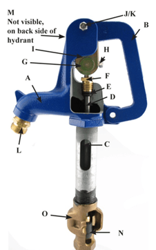
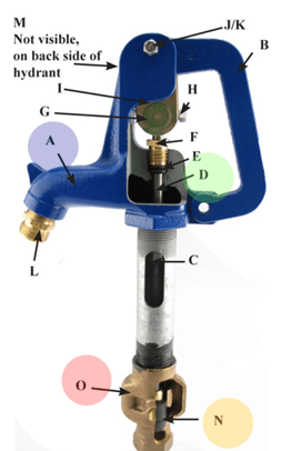
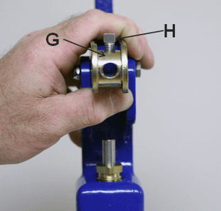
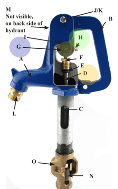
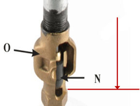
The rubber plunger (N) in the bottom of the hydrant can be lowered by raising the point of contact of the square head set screw (H) on the S.S. operating rod (D)
Using a 5/16” wrench, loosen the square head bolt so the handle can be moved up and down freely without moving the operating rod.
Step 2 & 3
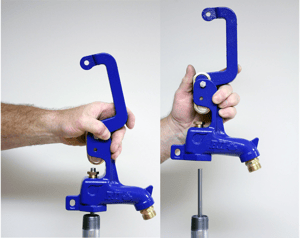
Lift the handle (B) to the fully open position.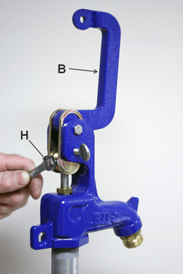
With the handle (B) up in the fully open position, tighten the square head bolt (H)
Step 4
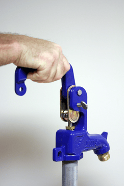 Apply closing pressure on the handle - this will force the operating rod to assembly / plunger (N) down-wards until it makes contact with the valve seat in the valve body (O). Do not force the handle down -when the handle stops moving you have positioned the plunger against the valve body seat. STOP!
Step 5
 5a - Set the closing pressure – To do so you must loosen the square head bolt again, allowing the handle to be moved up and down freely without moving the operating rod. – DO NOT MOVE THE OPERATING ROD FROM POSITION IN STEP #4
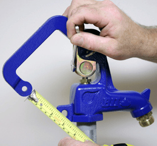
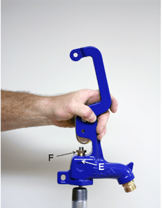
5b- Position the handle so that there is approx. 2” between the handle and the locking tab on the head casting.
Then using a 5/16” wrench, tighten the square head bolt so the handle will force the operating rod downward and apply pressure to close the handle.
Yard Hydrant is Leaking at the Stem Packing
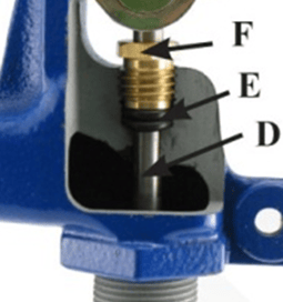
 The brass packing nut (F) has been factory adjusted. If leakage does occur it can be easily stopped with a slight adjustment to further compress the double O-Ring seal packing.
Step #SPA-1
Simply tighten the brass packing nut (F) by turning it clockwise in very small increments until the leakage stops using a ¾” open end wrench.
Caution: DO NOT over tighten packing nut. Excessive compression will result in accelerated wear and or possibly damage to the O-Rings.
Replacement of Yard Hydrant Head
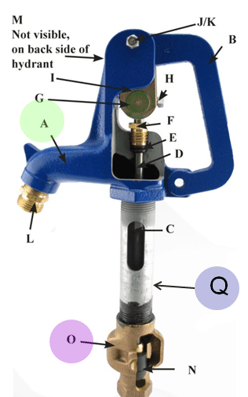 Sometimes, the hydrant head (A) must be removed due to damages or to replace the plunger (N).
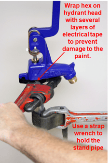
Do not place a pipe wrench on the galvanized stand pipe (Q), it will cause damage to the factory coating. To prevent the galvanized stand pipe (Q) from turning, use a strap wrench; this should also be followed if tightening the valve body (O).
It is VERY important that the first two steps be followed carefully to avoid the potential for serious complications.
Failure to do so could result in the plunger un-threading from the connecting rod which could be difficult to re-assemble, possibly resulting in the need to dig up the hydrant unnecessarily.
Step 1
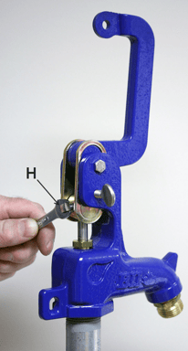 Loosen the 5/16”-18 UNC x ¾” 18.8 Stainless Steel Set Screw (H) to allow the 3/8” stainless steel operation rod (D) to turn freely in the zinc plated pivot connector (G)
Step 2
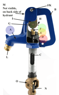 Loosen the ¾” brass packing nut (F) until it is not putting any pressure on the O-Ring seals (E) it is better to turn it out completely than to have pressure on the O-Rings which could result in the operating rod turning with the head casting (A) loosening the packing nut allows the 3/8” stainless steel operation rod (D) to turn freely from the head casting (A)
Step 3
 Remove the head casting (assembly) (A) by turning the head casting counter clockwise (lefty loosey) using a pipe wrench.
WARNING!
Make sure to monitor the 3/8” stainless steel operating rod (D) while turning the head casting off the pipe thread. The rod MUST NOT turn! If the rod turns it could unthread the connecting rod from the plunger (N) due to the snug fit in the valve body (O)
TIP! – place a cloth or soft leather or rubber sheet between the pipe wrench jaws and the head casting to prevent damage to the corrosion resistant protective paint coating.
Step 4
When the head casting (A) is free from the Galvanized stand pipe (Q) approx. 3 – 4 full revolutions, pull the head casting straight up.
At this point, you would be able to fix any damage within the hydrant or fully replace the head.
Step 5
 Make sure the 5/16”-18 UNC x ¾” 18.8 Stainless Steel Set Screw (H) is turned out to allow the 3/8” stainless steel operating rod (D) to slide freely thru the zinc plated pivot connector (G)
Step 6
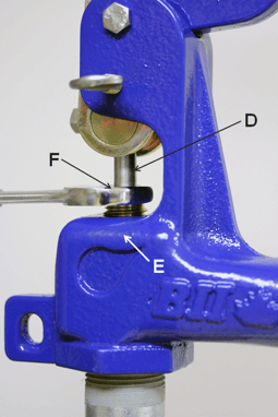 Make sure the ¾” brass packing nut (F) is loose and is not putting any pressure on the O-ring seals (E) to allow the 3/8” stainless steel operation rod (D) to slide freely thru the O-rings (E)
Step 7
 Lower the head casting downward so the 3/8” stainless steel operation rod (D) slides thru the O-ring seals (E) and the ¾” brass packing nut (F) and thru zinc plated pivot connector (G)
Step 8
 When the head casting (A) touching the Galvanized stand pipe (Q) apply P.T.F.E. (aka: Teflon) tape or pipe thread sealing compound to the pipe threads, turn the head casting clockwise engaging the threads making sure that they start freely by hand. Tighten using a pipe wrench (righty tightly) approx. 3 – 4 full revolutions until head casting is secure. NO NOT OVERTIGHTEN!
Step 9
 Tighten the ¾” brass packing nut (F) until it is putting pressure on the O-ring seals (E) often hand tight is enough NOTE: it takes very little compression to make a positive seal.
WARNING!
Over tightening of the packing nut can cause premature wear and damage to the O-ring seals. It is best to hand tighten at first and tighten further in small increments as required until any leakage is stopped when the water pressure is turned back on.
Step 10
 Adjust the hydrant setting following steps covered in “How do I adjust the hydrant if it has a drip or will not shut off completely?”
When adjustment is complete tighten the 5/16”-18 UNC x ¾” 18.8 Stainless Steel Set Screw (H) securely to the 3/8” stainless steel operation rod (D) in the zinc plated pivot connector (G) to prevent slippage of the rod in the pivot connector which would result in the loss of the hydrant setting. NOTE: The specially cupped set screw (H) grips very well on the rod so with moderate tightening of the set screw should be sufficient.
Do not leave hose attached to hose bib in freezing temperatures as it may prevent proper drainage of the shut-off valve.
If hose is attached to the hose bib of the hydrant when the hydrant is shut-off, back siphoning can occur if end of hose is left in container of liquid. The end of the hose must be left open to the air so hydrant can drain back. A back flow prevent should be installed if a hose is left on during the warm summer season.
Replacing the Yard Hydrant Plunger
Step 1
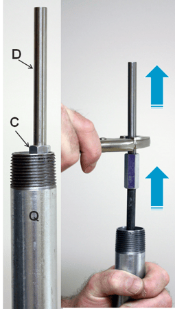 With the head casting removed the hydrant head casting removed, the S.S. operating rod (D) will be protruding out of the galvanized stand pipe (Q) approx. 3-1/2”
Pull the S.S. operating rod (D), coupling [C] connection rod [R] and plunger assembly straight up.
NEVER TWIST COUNTER CLOCKWISE, THIS COULD CAUSE THE PLUNGER TO UNTHREAD FROM THE ROD.
Step 2
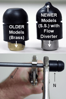 Grip the steel connection rod “R” with a vice grips just above the plunger (N), with a second vice grip securely grip the brass insert on the plunger assembly (stainless steel on newer models), then turn the plunger counter clockwise approx. 7-1/2 to 8 turns (about ½” thread) to unthread the plunger from the rod.
Step 3
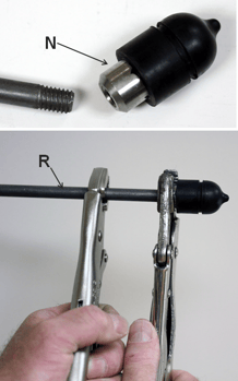 Keep the grip the rod “R” with a vice grips just above the plunger, with the second vice grip the stainless steel insert on the new plunger (N) securely and turn the plunger clockwise to thread it onto the rod.
Tighten securely.
Step 4
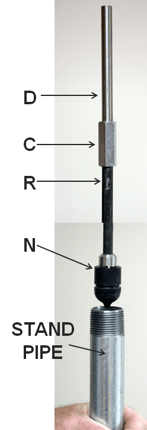 Remove both vice grips, and carefully lower the entire rod and plunger assembly (S.S. operating rod (D), coupling ©, connecting rod ® and plunger assembly (N)) straight down in the stand pipe until the plunger is pressed into the valve body (O) against the valve seat.
NEVER TWIST THE ASSEMBLY COUNTER CLOCKWISE, THIS COULD CAUSE THE PLUNGER TO UNTHREAD FROM THE ROD!
After this is complete, refer back to the Yard Hydrant Head installation instructions. This shows how to install the existing or a new head.
Have further questions about this subject?

Head over to Boshart's Knowledge Base: technical product information, guidelines, and more.
SHARE