In this Webinar, we discuss what an Industrial Pitless Unit is and the industry certifications. We then explore Discharge Housings, Spool Types, Well Caps and QA procedures. Check it out at the video below!
.png?width=400&name=My%20Post(276).png)
 For a step by step walk through on how to properly fill out the industrial pitless unit quote forms, check out our blog How to Accurately Fill Out the Industrial Pitless Unit Quote Forms.
Transcript
Good morning everyone, welcome to our webinar on Industrial Pitless Units. We’re happy you were able to join us today.
My name is Braedlyn McEwen and I am the Social Media and Content Coordinator here at Boshart Industries. I am joined today by our Tech team, Will Bender our Quality Assurance Analyst, Steve Hudson our Quality Assurance Manager and Paul Erb our Research and Development Manager. They will help answer your questions at the end of the presentation. Any questions we cannot get to, we will reach out following the presentation.
Throughout the presentation you can type out any questions that you have.
You should see a side bar on the right hand side of your screen.
If you click on the top button, which looks like an arrow in a box, it will open up a little menu with a question box which you can type your questions and we will be able to see them.
Please note the slide number if you’re referencing a specific slide. The numbers will be displayed on the bottom left of the slide.
Overview
To start off the presentation, we will take a look at what an industrial pitless unit is and the industry certifications. Then onto the Discharge Housing, Spool Types, Well Caps and QA procedures. We will then finish the presentation with any questions.
Let’s get started!
First, let’s explore exactly what a pitless unit is.
What is a Pitless Unit?
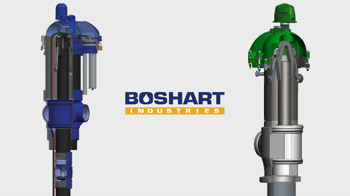
Industrial pitless units eliminate the need for well pits or the need for additional buildings for Industrial and Municipal well installations. This photo shows the above ground portion of the Pitless Unit after installation is completed. Our units are available in Stainless and Ductile and range from 5” to 12” sizes and are available in 3 foot to 10 foot bury lengths.
The discharge housing and spool components of the Industrial Pitless units create a two piece 90° elbow to direct the flow of water from the submersible pump into the service line buried below the frost line to prevent freezing. An upper barrel extends the well casing to the surface for easy access to the well and an additional 2 ft. above ground section prevents surface water from contaminating the well.
This animation shows the key components of a well installation, the pump column which consists of the submersible pump, drop pipe and electrical cable are supported by the pitless adapter spool. The spool is sealed to the discharge housing by O-rings. A crane is attached to the lift out assembly to lower the pump column into the well for installation. When the pump requires service or replacement the pump column is lifted to pull the pump to the surface.
Boshart Pitless Units are fully certified to the NSF-61 standard, with no minimum daily flow rate requirements, NSF-372 No lead, Water Systems Council PAS-97, ASSE 1093, Hydrostatic Pressure tested under PAS 97 and they meet the Great Lakes Upper Mississippi River Board requirements.
Discharge Housings
The clear- way discharge housing design has no reduction in size, providing full bore passage through the discharge housing for pump installation or well rehabilitation . This animation shows the insertion of a protective sleeve of equal size to the well diameter that protects the O-ring seats when equipment, like a brush, is lowered through the discharge housing for cleaning the casing or well screens.
The threaded connections in the discharge housing are specially designed to ensure the full thread of the weld nipple and upper barrel are fully protected in the housing. The wall thickness increases as the thread tapers, providing a thicker cross section. By engaging all the threads, the joint strength is increased and the risk of failure due to corrosion is greatly reduced increasing the life expectancy over others that have exposed threads.
Standard units are shipped with a weld nipple for direct welding onto the well casing, if a threaded connection is desired simply remove the weld nipple and thread the housing onto the well casing.
The Standard unit is designed to be welded to the well casing. Several other options are readily available as accessories to attach the unit to the well using a Class 150 Flange, EBAA Mega Flange or a Mechanical Joint.
In addition to the traditional installations, these units can be easily converted to attach to PVC well casing or to different casing materials using isolation flange kits to eliminate any risk of galvanic corrosion between steel casing and a stainless steel pitless unit.
Standard Unit
The Standard unit is supplied with a threaded discharge connection, several other options are readily available as accessories to convert the connection to the service pipe to a Class 150 Flange, a plain end nipple for welding or use of a Mechanical Joint, the discharge can be easily reduced or increased to desired pipe diameter by using swage nipples.
These add-on accessories are quoted and sold separately, they are included on the second page of the order forms for easy reference and quoting.
The globe design ensures the O-ring is not compressed as it passes by the discharge port eliminating any chance of the O-ring getting cut during installation.
The large 360° water passage provides additional safeguards to ensure sufficient water flow in the event that the spool is not properly aligned for optimal water flow. To ensure minimal friction loss, the best practice is to align the flow passage in the spool directly with the discharge outlet in the housing. Following the installation instructions will ensure proper alignment and a trouble-free operation.
Staggered seating of the O-rings reduces the force required to seat the O-rings. You can see in the animation that the top O-ring is just above the upper seat area as the lower O-ring is being compressed into the bottom seat.
Spool Types
Boshart has two spool types designed for specific well installations. Normal Well Spools are used in wells where the static water level is below the Pitless Unit, whereas Flowing Well Spools are required for wells where the water is being pushed up to the surface and flowing from the top of the well casing.
Normal Well Spools have large crescent shaped through passages, sometimes referred to as equalization passages, providing large open areas through the spool into the well. Heavy Gauge Flat Jacketed Pump Cable and other equipment such as PVC probe tubes for sensors can be easily inserted through the spool.
Flowing well spools have a solid top with multiple threaded ports for installing cable seals for a water-tight seal around pump cable and sensor wires preventing water from flowing from the well into the upper barrel. The sealed spool confines the water in the well below the frost line.
This cut away of the spool shows how the probe tubes align with the cable seals inside the spool. The flowing well spools allow for multiple PVC tubes to be inserted into the bottom of the spool without the need to have custom threading on the bottom plate. The tubes are secured in position, in alignment with a sensor cable seal port by fastening them to the drop pipe with cable ties, stainless clamps or pipe wrap tape.
The “Pressure Zone Tapings” allow for installation of a sampling faucet and additional pressure sensing equipment.
The optional water sampling valves, provide a means to acquire a water sample at the well head. The water sampling valve kit has a non-freeze design which allows for sampling in all seasons.
All spools include the O-ring number for easy identification.
Off the shelf American Standard, NBR O-rings are readily available for 5”, 6” and 8” Pitless Units
O-rings for 10” & 12” Pitless units are custom made from North American Standard Cord
All our Pitless Units are provided with Lift Pipes complete with Hold Down Hooks as standard equipment.
Hold Down Hook Benefits
Hold down hooks prevent damage to well components and eliminate the risk of personal injury due to these three conditions:
- Prevents pump column from rotating due to locked rotor condition which would result in damage to the pump power cable.
- Prevents lift out of pump column due to thrust pressure against the spool created by start up of high horse power and capacity pumps.
- Prevents the lifting of the pump column and spool from the well due to internal well pressure created in flowing wells.
Hold down hooks also have an additional benefit, they can be engaged and tightened to seat the O-rings. By tightening the nut on the J hooks, it will force the O-rings to seat in the discharge housing. In the majority of installations, the weight of the pump column will seat the O-Rings with out the aid of the J hooks.
The hold-down pods double as anti-slip lifting pods eliminating the risk of slippage of lift straps which could result in accidental dropping the Pitless Unit during the positioning and welding process to the well casing during installation. Safety of workers is a key reason for making the hold down assembly system standard equipment on all units.
Well Caps
The well caps are constructed from heavy duty cast iron, with powder coat finish for corrosion resistance. The sealing gaskets are very robust and moulded from Buna-N rubber for excellent sealing. All nuts, bolts, locking pins and 24 mesh vent screen are stainless steel.
Boshart Well caps are designed with a 4” FPT conduit connection which provides ample room to install the heaviest of pump cable with ease. Optional cable seals provide a water tight, vermin proof, sanitary barrier between the conduit and the well chamber. Conduit Cable Seals are available for all pitless units and have power cable holes to seal 14 gauge to very heavy 4 ott pump cables.
The conduit can be split into two conduit connections by installing an optional Conduit adapter. It provides a 2” power cable conduit and second 1” conduit for transducer or other sensor cables. Sensor wires should be run in a separate conduit to reduce the risk of electrical interference.
The 2” cast iron well cap vent comes complete with a locking pin preventing any tampering. The screen is a 24 mesh and covers 9 and ¾ square inches exceeding the requirements of the most stringent State and Provincial well construction regulations. Venting of the well is crucial to allow the well to breath. The vent avoids the creation of a vacuum in the well during the pumping cycle due to the drop in the water level. Equally important is the air in the well must be able to escape as the water level in the well rises back to the normal static water level after the pumping cycle.
The well caps are lockable and tamper proof. Two heavy duty stainless steel locking pins secure the top cover, making it impossible to gain access to the well chamber even if all the bolts are removed.
Since not all well installations are regularly monitored, the vent and two accessory port caps are locked with internal SS locking pins. For installation where frequent monitoring of the well is required, these pins can be removed from the two accessory port caps and replaced with external heavy duty stainless steel locking pins making it impossible to gain access to the well chamber, however access can be quickly gained by unlocking and removing the thread cap.
This animation demonstrates, the removal of the locking pin and cap from one of the two access ports, with the cap removed, sensors can easily be inserted into the probe tube which guides the sensor down through the spool and down the well free of interference pump cable or getting caught between the pump column and the well casing. It is fully protected by the probe tube which extends down the well as far as the sensors are going to be set.
We now have a quick question on your screen. We will give you a minute to answer!
The answer is all of the above! Thanks to everyone who participated.
Quality Assurance Practices
All Boshart Pitless units are fully certified to NSF 61 standards including the blue epoxy coating. Ductile units are coated on both the inside and outside and stainless units are coated on the outside only.
Every spool has precision machined O-ring grooves, our ductile iron spools have epoxy coating in the O-ring groove for maximum corrosion resistance.
Each pitless unit is closely inspected before sending out the door. A QA employee inspects each component of the unit and fills out a checklist on the quality management system. This keeps a permanent quality assurance record for each individual pitless unit.
The info tag is included on every pitless unit for easy identification.
Here is an example of a four page submittal drawing that we offer for every size and variation of pitless units. These submittals cover all the certifications, dimensions and specifications of the pitless unit as well as detailed information on the spool and well caps, everything typically required by the engineering firm.
Boshart can provide detailed CAD and or dimensional models for the Pitless Units to engineering firms specifying our units if needed. This requires the completion of a Non-Disclosure Agreement prior to sharing any proprietary information.
Boshart is happy to provide an Industrial Pitless Booklet. The booklet contains all the technical information regarding pitless units, including drawings, dimensions, detailed parts breakdown along with installation instructions for the units, well caps and all the optional accessories. This 87 page booklet brings everything needed together into one single booklet that can be downloaded following the presentation.
We also have quote forms available for all well sizes to make ordering a breeze. Quote forms will be available to download on BoshartU following the presentation.
We will now take the time to answer any of your questions that came up during the presentation. Any questions we cannot get to, we will address after the presentation.
We will give you a minute to type out your questions.
Conclusion
That is the end of the presentation today. You can learn more about the features we offer at Boshart’s as well as other useful information on plumbing and water well products.
At BoshartU, our goal is to equip you and your team with the knowledge you need to be more successful.
We regularly publish new blogs and content that will help you become more comfortable and confident with our products.
Be sure to follow Boshart Industries on Instagram, LinkedIn and Facebook to stay connected with us.
Thank you again for joining us today.
Check out our website for more product specs, and subscribe to our blog to receive new content updates.
Enjoy the rest of your day!
Have further questions about this subject?

Head over to Boshart's Knowledge Base: technical product information, guidelines, and more.
SHARE